
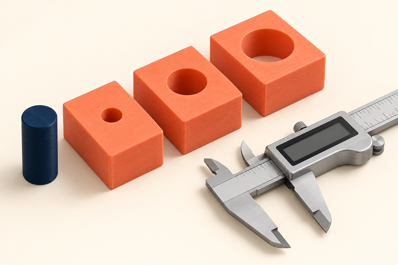
A peg and a hole can look perfectly matched on screen and still refuse to fit after printing. The CAD dimensions describe the intended geometry; the printed surfaces also reflect your material, orientation, calibration, and slicing settings. A short fit test helps you choose a useful gap before printing a complete enclosure, organizer, or sliding part.
The goal is to test one interface. You do not need the whole design to learn whether a tab enters a slot or a round peg slides through an opening.
Clearance and tolerance mean different things
Clearance is the designed space between mating parts. Tolerance describes the permitted variation in a dimension. In everyday printing conversations the words are often mixed together, but separating them makes your measurements easier to understand.
For a nominally round 10.00 mm peg inside a 10.40 mm hole, the diametral clearance is 0.40 mm. If the peg is centered, that gives 0.20 mm of radial space on each side. Writing only “0.2 mm clearance” leaves an important ambiguity.
Use these simple relationships for the intended CAD dimensions:
- Diametral clearance = hole diameter − peg diameter.
- Radial clearance = diametral clearance ÷ 2.
- For a centered rectangular tab, per-side clearance = (slot width − tab width) ÷ 2.
Choose the behavior before choosing the number
Describe what the joint should do. A removable tray insert should lift out easily. A sliding guide should move without binding. A locating peg may need to limit wobble. These are different acceptance criteria, even when their drawings look similar.
There is no clearance value that works for every printer and geometry. Prusa’s modeling guidance identifies orientation, material, calibration, settings, and the shape of the interface as factors, and recommends iteration. Treat the following dimensions as a test series, not a recommended final fit.
Build a small comparison in SimplerCAD
As an example, use one nominal 10.00 mm diameter peg and three separate small blocks with through-holes. Give each block the same outer dimensions and thickness; 20 × 20 mm with 5 mm thickness is a convenient modeling exercise. Make the peg long enough to hold while testing and keep it separate from the blocks.
| Sample | Hole diameter | Diametral gap | Gap per side when centered |
|---|---|---|---|
| A | 10.20 mm | 0.20 mm | 0.10 mm |
| B | 10.40 mm | 0.40 mm | 0.20 mm |
| C | 10.60 mm | 0.60 mm | 0.30 mm |
Create a Box and a Cylinder cutter for the first block. Set the cutter’s circular diameter, align it, and extend it beyond both faces before subtracting. Keep an uncut copy or a saved starting version so you can produce the other hole sizes without rebuilding the test. Name the objects A, B, and C and keep a matching note beside the physical samples.
The manual’s Create, Boolean, and Measure sections explain the relevant controls. Check each hole’s intended size before export; changing the whole block’s scale would also change its outer dimensions.
Print under conditions that match the final part
Use the intended printer, material, orientation, and slicer settings. A vertical test hole does not fully represent a hole that will be printed horizontally. Similarly, a short test opening may feel different from a long guide because the contacting length changes.
Let the samples cool, identify them, and try the same peg in each. Record whether it will not enter, enters with resistance, slides freely, or has more play than the design allows. Note whether resistance occurs only near the first layer or along the full length. Avoid forcing a sample and then treating the damaged fit as the result.
Record a result you can reuse
Keep the CAD dimensions, printer, material, orientation, layer height, relevant compensation settings, and observed behavior together. “Sample B slides freely with this profile” is more useful than “0.4 mm always works.” If all three samples bind or feel loose, expand the series in the appropriate direction.
Apply the chosen starting clearance to your real design and test the actual joint. Where possible, print just that portion with its final wall thickness and engagement length. Keep the mating feature’s center and location fixed while changing its size, so the experiment measures fit rather than alignment.
Open SimplerCAD to build the small test first, and save it alongside the project it informs.