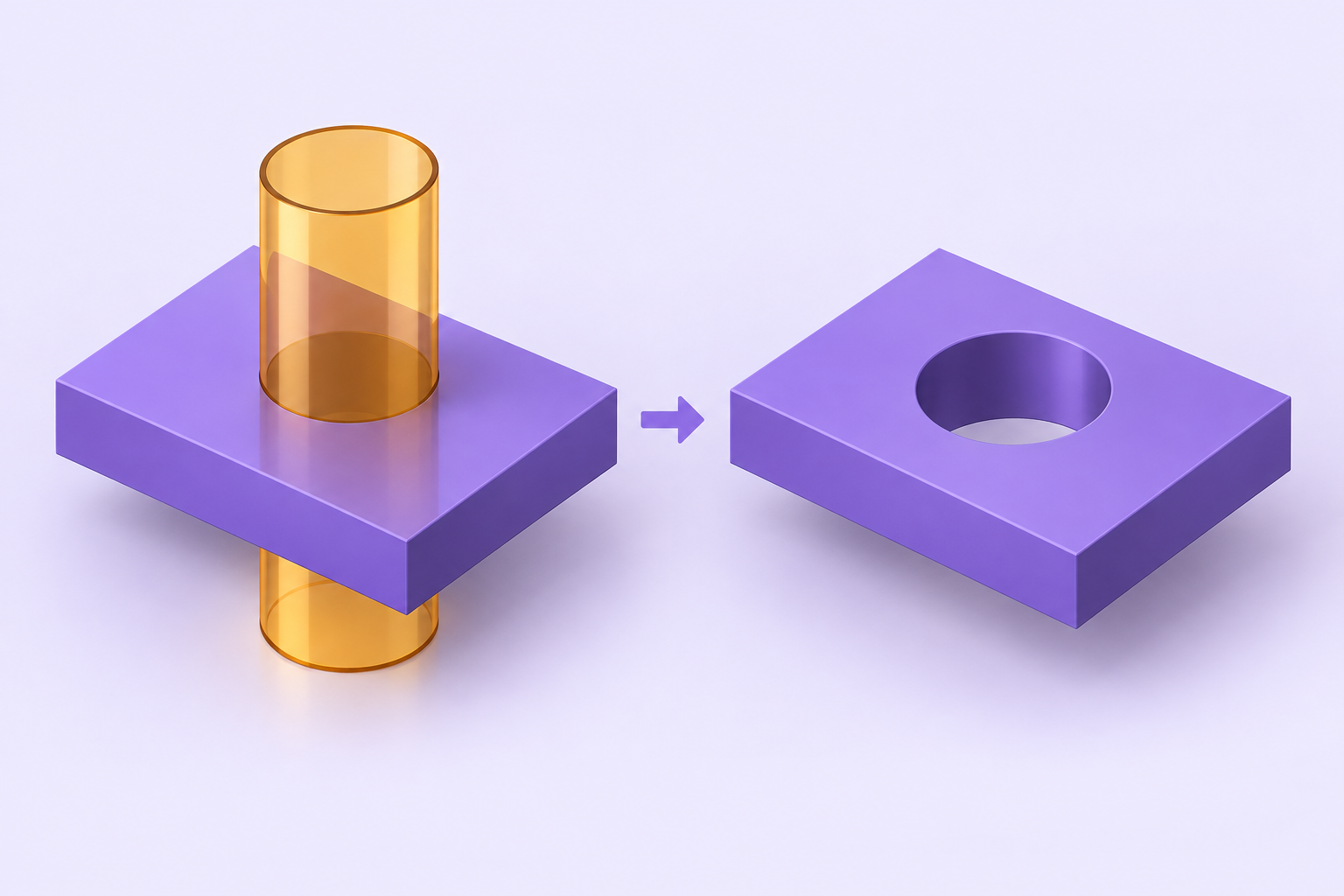
You place a cylinder over a plate, apply Subtract, and expect a hole. Instead, the plate looks unchanged, the wrong object disappears, or the opening stops halfway through. These results can have different causes. Check the relationship between the two solids before changing several settings at once.
A Boolean subtraction removes the tool’s overlapping volume from the target. The target is the part you want to keep; the tool, often called the cutter, describes the space you want removed. Keeping those roles clear is the first step toward a predictable result.
Start with a saved version
Save the project before experimenting, especially when working with an imported mesh. Give the two objects descriptive names such as “Plate target” and “Hole cutter.” If a result is wrong, undo it and inspect the original pair. Repeating Subtract on an already altered result makes it harder to isolate the cause.
1. Confirm which body is being cut
Read the target and tool shown by the Boolean operation. A plate minus a cylinder produces a different shape from a cylinder minus a plate. Use the operand-swap control if the roles are reversed.
Choose the operation that matches the task. Ordinary Subtract removes the overlapping tool volume. Intersect keeps the shared region, and Union combines volumes. A specialized operation with a similar name is not a general substitute for a missing or misplaced cutter.
2. Check overlap in two views
Objects can overlap in the camera view without touching in 3D. Look from above to inspect the hole’s location, then from the side to inspect the cutter’s depth. For a through-hole, extend the cutter beyond both surfaces. Merely touching a face does not describe a positive volume to remove.
For example, if a practice plate occupies heights from 0 to 4 mm, a vertical cutter could extend from −1 to 5 mm. Its length is then 6 mm, and it clearly crosses the whole plate. The extra millimetre at each end is illustrative; the important relationship is that both ends lie outside the target.
3. Distinguish a through-hole from a pocket
If the cutter ends inside the plate, the result may correctly be a blind pocket. Decide whether you want an opening all the way through or a recess with a floor. For a recess, the lower cutter face determines the remaining floor thickness. Check that distance explicitly.
A cut that looks successful from above can still leave a thin membrane underneath. Inspect the underside before export, and examine the sliced layers later. Changing camera shading does not remove an unintended floor.
4. Check whether the retained cutter is hiding the result
If you chose to keep the cutter, it may remain inside the new opening. Hide it or move it aside, then inspect the target again. Also look for a duplicate of the original uncut plate occupying the same position. An intact copy can conceal a correctly cut object.
When inspecting, identify objects by name rather than repeatedly clicking the same overlapping area. Keep reference copies clearly named and separated from the export candidate.
5. Isolate problems in imported geometry
If the same cutter works on a simple box but not on your imported part, investigate the target mesh. Run Print check and read the reported issues. Save a separate version before Repair, Make solid, or other geometry-changing operations, then compare small openings and edges afterward.
Repair and simplification address different problems. Reducing triangles may make a dense object easier to process, but a smaller triangle count alone does not prove that the mesh is valid. Conversely, a repaired surface can still contain more detail than you need for the edit.
Try one simple cutter first. If that succeeds, add complexity gradually. This gives you a useful dividing line between a basic placement problem and an operation involving difficult geometry.
Match the symptom to the next check
- The wrong object remains: inspect the target/tool order and operation type.
- Nothing seems to change: inspect actual overlap, retained cutters, and duplicate objects.
- The hole is only a recess: check where the cutter ends inside the target.
- A complicated cut fails: try a simple cutter on a saved copy and review mesh issues.
- The STL contains extra parts: check whether you exported the whole scene or only the finished selection.
Finish with the actual result
Measure the opening, inspect it from both sides, and run the relevant geometry checks. Save the finished project before exporting. Open the exported file in your slicer and check that only the intended part is present.
The SimplerCAD manual explains Boolean operations and mesh tools. For a small practice model, follow the plate-and-hole tutorial, then change one cutter position to see how the result responds.