Tutorials
SimplerCAD tutorials
Learn a complete modeling workflow: navigate a scene, define a part, inspect its geometry, and export a separate file for the next stage. Keep this page beside the workspace as you practice.
For individual controls and shortcuts, use the feature manual. For file choices and common problems, use Resources.
Practice dimensions, alignment, and subtraction
Use a rectangular plate with a central hole to learn how a cutting tool removes volume. The dimensions below are practice values; choose dimensions and clearances for your actual use separately.
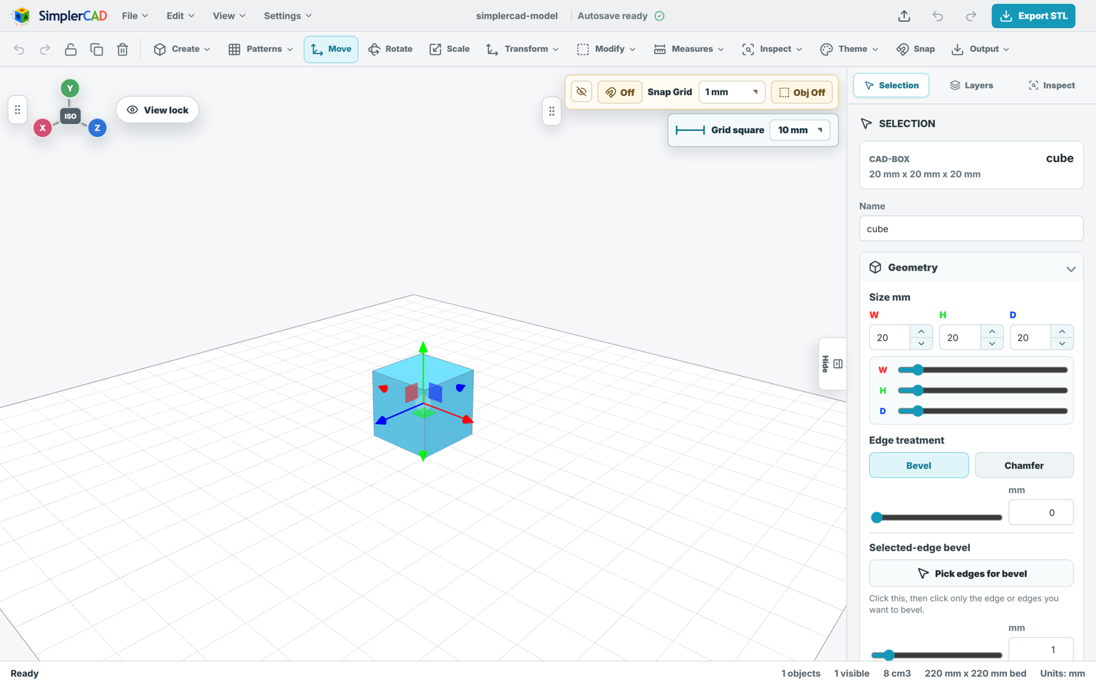
- Define the base. Choose millimetres and add a Box from Create. Use the inspector to make a plate with a 50 × 30 mm broad face and 4 mm thickness. Orient the broad face flat on the bed, use Floor, then Center.
- Make a separate cutter. Add a Cylinder with a 5 mm circular diameter and a length greater than the plate thickness. Orient its axis perpendicular to the broad face. Its intersection with the plate defines the removed material.
- Align before cutting. Center the cylinder against the plate along the two directions of the broad face. Position it completely through the plate, with an end beyond each surface. Inspect a top view for centering and a side view for penetration.
- Subtract. Use Boolean Subtract with the plate as the target and the cylinder as the tool. Check operand order and swap if needed. If you keep the cutter, move it away afterward so it does not obscure the hole.
- Measure and inspect. Look through the opening from both sides. Check the outer dimensions and feature placement with the measurement tools. If the result is wrong, undo and correct the cutter before repeating the operation.
Try one deliberate variation: save the starting project, then create an off-center hole or a second opening. Decide its position before moving the cutter and measure afterward.
References: Create, Align, Boolean operations, and Measure.
Inspect an imported model before editing
- Choose the information you need. STL suits shape-focused printing workflows. GLB is useful when appearance matters. For OBJ, keep its matching MTL together with the model; supported OBJ + MTL ZIP imports preserve that relationship. Read the file formats guide before converting unnecessarily.
- Check a known dimension. Use Fit view and inspect Dimensions. Compare a measurement with the original design. A unit mismatch can create a plausible-looking model at the wrong physical size.
- Orient and position. Use standard views to identify the intended bottom. Rotate if needed, use Floor, and inspect from the side before editing the mesh.
- Keep the starting version. Save the project before changing geometry. Give the working copy a useful name, such as “mounting-plate-larger-hole.”
- Make one focused edit. Change the feature you need. If the mesh is dense, consult Modify before reducing or remeshing. Compare small features before and after; simplification can change them.
If an import looks wrong, check file type, size, orientation, and companion material files first. Importing it repeatedly will not fix a missing MTL or a units mismatch.
Check the model and prepare an export
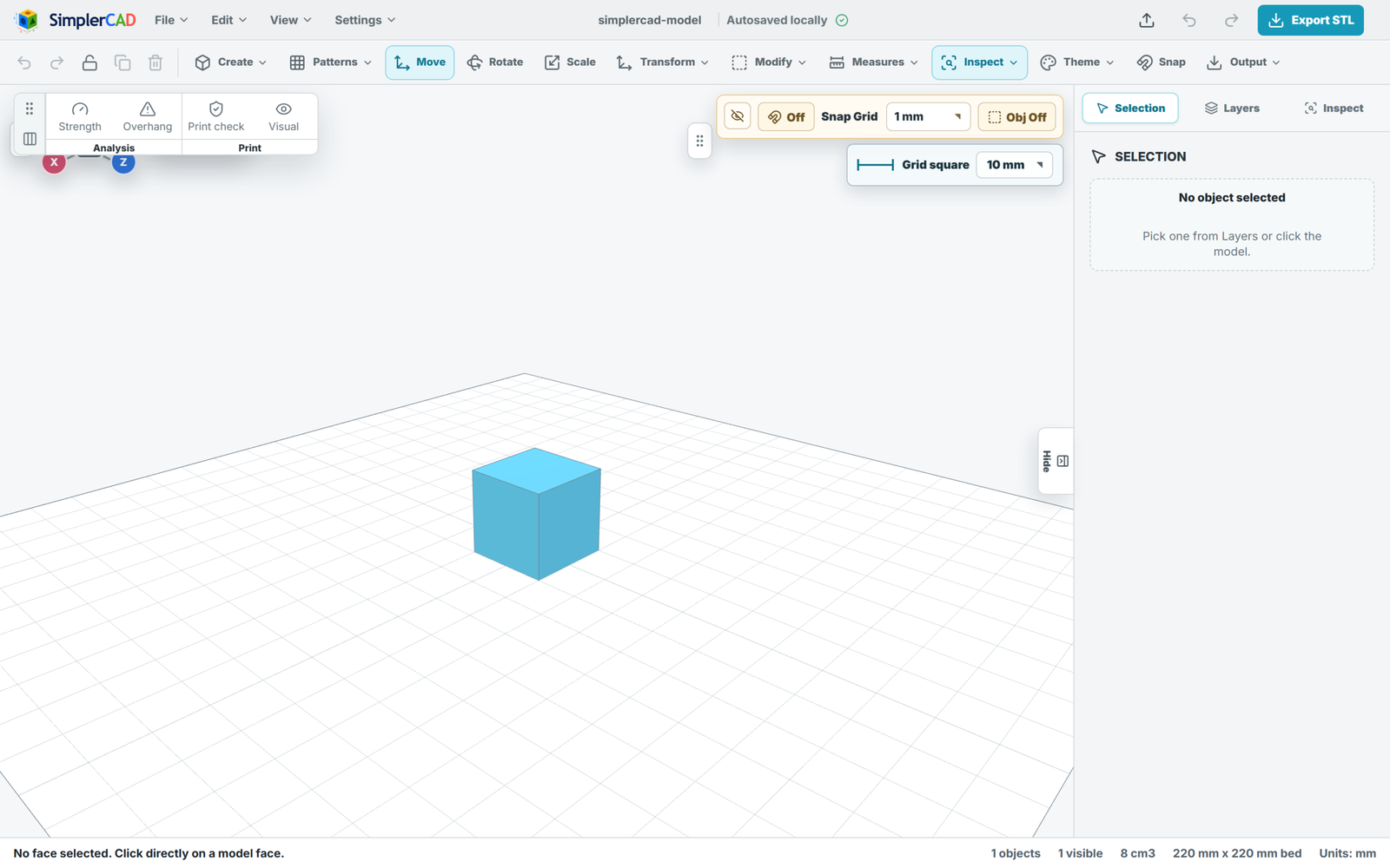
- Inspect final geometry. Look at thin walls, openings, and joins. Run Print check and review topology or manifold issues. If you apply Repair, inspect the affected geometry and rerun the check.
- Review print orientation. Use overhang analysis to find surfaces that may need support. Consider orientation in your slicer too; fitting the bed does not settle the support strategy.
- Review relative strength where relevant. Compare highlighted sections with intended use. Make one focused change, such as widening a narrow connection, and compare again. Read the strength-map guide for limitations.
- Save the editable project. Keep a project version before export. A mesh export serves a different purpose from the project you reopen for further work.
- Choose export scope. Export the selection or whole scene as appropriate. Exclude spare cutters and reference objects. Choose STL for a typical slicer workflow, or GLB/OBJ when the receiving program needs those formats.
- Inspect the exported result. Open it in your slicer or viewer and recheck size, orientation, and included objects. Review generated layers and print settings before printing.
Geometry checks and relative strength analysis support design decisions. They do not establish a manufactured part’s load capacity or physical fit. Material, print settings, and real use still matter.
References: Analyze and print checks, Projects, and Export and output.
Keep learning
Resources brings together file choices and troubleshooting. Contact SimplerCAD with a specific product question.